Understanding Marine Fire Control Signs A Practical Guide
Introduction
Picture a fire breaking out in a machinery space while a mixed crew and local firefighters rush on board. In that moment, understanding marine fire control signs decides whether everyone moves with confidence or wastes seconds guessing where to go. When we talk about understanding marine fire control signs, we are really talking about clear directions in the middle of chaos.
On most vessels the crew speaks several languages, and shore-side responders may have never stepped on that ship before. Standardized fire symbols turn the ship into a map that everyone can read the same way. These symbols come from SOLAS, the International Maritime Organization (IMO), and ISO standards, and they guide people to fire-fighting equipment, structural fire protection, detection systems, and escape routes without a single spoken word.
As ship owners, operators, or marine safety managers, we work under strict regulatory pressure, and for good reason—research shows that advancing maritime safety through early detection and standardized systems significantly reduces fire-related casualties at sea. Fire control plans must follow rules under SOLAS Chapter II-2, and vessels built after 1 January 2004 must apply IMO Resolution A.952(23). At Safety Sign Hub, we work with these frameworks every day, so we see how much easier inspections and real emergencies become when a vessel has clear, compliant marine fire control signs.
By reading this guide, we will walk through the full picture of understanding marine fire control signs. We will cover the regulatory base, each major symbol group, how color and annotations work, how plan symbols turn into real-world SIS signs on board, and what good compliance looks like in practice. We will also show how Safety Sign Hub helps vessel operators keep signs aligned with IMO and SOLAS requirements, so fire symbols actually work when they matter most.
As many ship safety auditors like to remind crews, “A fire plan that nobody can read is no fire plan at all.”
Key Takeaways
Marine fire control signs come from SOLAS and IMO rules, and ships built after 1 January 2004 follow Resolution A.952(23). Knowing which standard applies to a vessel makes both inspections and emergency planning far smoother. It also gives us a clear checklist when we review a ship’s fire control plans.
Standard graphical symbols remove language barriers during an emergency. A firefighter from another country can read the same plans as the crew and understand them. That shared understanding keeps everyone working from one mental picture of the ship.
When we start understanding marine fire control signs, we see four main groups of symbols covering structure, fire-fighting appliances, detection and alarms, and escape routes. Each group plays a different role in controlling or escaping a fire. Together they form a complete safety map of the vessel.
Color bands and letter codes give instant detail, such as which extinguishing medium is used or which space a damper serves. Numbers add information about capacity, quantity, or equipment ID. This extra detail lets officers and responders plan the right action without reading long notes.
Real compliance depends on more than buying signs and sticking them up. We need accurate fire control plans, correctly placed SIS signs, and crew who practice using them in drills. Working with a specialist like Safety Sign Hub helps keep all three parts aligned with current IMO and ISO requirements.
The Regulatory Foundation For SOLAS IMO And ISO Standards
Fire control signs do not exist in isolation. They sit inside a strict framework built to make ships safe and to give inspectors and responders a common reference. When we start understanding marine fire control signs, we need to start with this framework, because it explains why certain symbols, colors, and layouts are non‑negotiable.
SOLAS Chapter II‑2, Regulation 15.2.4 requires that fire control plans are permanently displayed on board. These plans must show fire-fighting equipment, structural fire protection, detection systems, and escape routes for every deck, and a duplicate set must be kept outside the deckhouse in a marked, weathertight box. This second set is there so shore-side responders can act even if the inside of the vessel is inaccessible.
The IMO develops and maintains the symbol sets that appear on these plans, while ISO publishes closely aligned technical standards. At present, inspectors expect vessels to follow this combined approach: SOLAS for the legal requirement, IMO resolutions for the symbol language, and ISO standards for detailed design and application guidance.
As the IMO consistently points out in its guidance, clear documentation and signage are central to effective shipboard fire safety.
IMO Resolution A.952(23) The Current Standard
IMO Resolution A.952(23) is the modern baseline for shipboard fire control symbols. Adopted in 2003, it applies to ships built on or after 1 January 2004 and replaces the older Resolution A.654(16) for new construction. When we are understanding marine fire control signs on a newer vessel, this is the resolution we are dealing with in practice.
The goal of A.952(23) is simple: build one graphical language that any trained person can read, regardless of flag or working language. Symbols for fire pumps, doors, dampers, detectors, and escape routes are standardized so they look the same on every compliant ship. Later, IMO Resolution A.1116(30) pulled these symbols into a wider family of shipboard safety signs, often called SIS signs, without changing the graphics themselves.
Older vessels may still carry plans built on Resolution A.654(16), so surveyors and port state control officers sometimes need to interpret both symbol sets. Even then, A.952(23) is now the reference point for new plans and corrections.
ISO Standards 17631 And 24409
ISO standards sit alongside IMO rules and make them practical on the drawing board and on the bulkhead. ISO 17631:2002 gives detailed guidance for fire protection plans, life‑saving appliances, and escape routes. Its symbols largely match those in IMO Resolution A.952(23), so when we follow ISO 17631 we stay aligned with IMO expectations.
ISO 24409 deals with shipboard safety signs installed at equipment locations. This standard describes how SIS signs should look, how large they should be, and how they should perform, including photoluminescent properties and durability in a marine environment. When we buy or specify signs that comply with ISO 24409, we make it far easier to show that our physical signage supports the SOLAS fire control plans.
Understanding Structural Fire Protection Symbols
Structural fire protection is the quiet backbone of shipboard fire safety. Before anyone picks up a hose or triggers a fixed system, the ship’s walls, decks, and doors are already working to keep a fire contained. When we focus on understanding marine fire control signs, we need to read these symbols first, because they show where fire is meant to stop and where it can spread.
On a fire control plan, lines and simple icons describe fire-rated divisions, fire doors, and main vertical zones. Taken together, they show how the vessel is divided into sections that slow or block a fire. They also reveal where ventilation can be controlled, which is vital for cutting oxygen to a burning compartment.
Fire-Resistant Divisions A-Class And B-Class
A‑class and B‑class divisions are the main structural tools for keeping a fire in one place. On the plan, A‑class divisions appear as thick solid lines and usually represent steel or equivalent construction that can stop smoke and flame for at least 60 minutes. B‑class divisions show as thinner solid lines and are rated to prevent flame passage for at least 30 minutes.
Main vertical zones are also marked, often by a dashed line with small circles, and they divide the ship into large fire sections from bottom to top. When we are understanding marine fire control signs on a deck plan, these main vertical zones help us see how a fire might be boxed into one part of the vessel. Keeping penetrations sealed and not compromising these divisions with unapproved openings is key to keeping that design working in real life.
Fire Doors And Their Operational Characteristics

Fire doors sit inside these divisions and can either support or destroy a containment strategy, depending on how they are used. On the plan, symbols show whether a fire door is hinged or sliding, and the symbol also indicates the direction in which the door opens. Letters and small marks on the symbol tell us more about how that door behaves.
A fire door marked with a small “C” is self‑closing, which means it should swing shut on its own when released. The letters “WT” show a watertight fire door, while “SWT” stands for a semi‑watertight door that offers both fire and water protection. When we practice understanding marine fire control signs, we teach crew to match each symbol on the plan with the real door on board, so they know which doors must stay closed at sea and which can be used during an evacuation without destroying the fire boundary.
Ventilation Control Systems
Ventilation can either feed a fire or help starve it, and the symbols for remote controls and dampers matter for both reasons. On the plan, colored circles with letters show where a remote control affects ventilation to a certain type of space. Blue with an “A” marks accommodation and service areas, green with an “M” marks machinery spaces, and yellow with a “C” marks cargo spaces.
Symbols also show the location of controls for skylights, dampers, and closing devices on inlets and outlets. Identification numbers on these symbols match markings on the actual dampers or controls, so we can link the drawing to the real handle or switch. When we are understanding marine fire control signs, learning these ventilation symbols helps us shut down air to a fire from a safe area instead of sending crew into smoke just to close a damper.
Fire-Fighting Appliances And Systems As Your Arsenal Against Fire

Once a fire is detected and boundaries are understood, attention shifts to the active systems that can fight it. This is the largest group of symbols on any fire control plan, and it covers pumps, hydrants, fixed extinguishing systems, portable units, and fire lockers—the marine fire safety system market continues to grow as vessels adopt more sophisticated protection technologies. When we work on understanding marine fire control signs, we treat this group as our arsenal map during an emergency.
The plan shows not only where each item is located but also how they connect, what medium they use, and how they are activated. Reading these symbols as a whole lets officers plan attack lines, choose the right extinguishing agent, and understand backup options if one system fails.
Water-Based Fire-Fighting Systems
Water remains the main fire-fighting medium on most ships, and its delivery systems have their own set of symbols. The main fire pump usually appears as a circle with a dot in the center, located in the engine room and supplied by the ship’s main power. The emergency fire pump uses the same base symbol but is drawn within a larger circle, showing that it sits in a separate space with its own power source.
Next to these symbols, the plan should indicate pump type, flow rate, and pressure head, either as text or in the legend. Fire mains are shown as lines, often with small circles for hydrant outlets, and section valves appear with symbols and ID numbers so they can be isolated if part of the line is damaged. The international shore connection has its own symbol, marking the fitting where shore fire brigades can connect their water supply to the ship. When we train officers on understanding marine fire control signs, we spend time on these water system symbols, because they show how to keep water flowing even when part of the ship is compromised.
Fixed Fire-Extinguishing Systems
High‑risk spaces like engine rooms, pump rooms, and some cargo holds are protected by fixed extinguishing systems. On the plan, these appear as square symbols, often with a colored inner circle and a letter indicating the extinguishing medium:
Grey with “CO2” or “N” – carbon dioxide or nitrogen
Yellow with “F” – foam
White with “P” – dry powder
Brown with “H” – Halon or similar gases
Green with “W” – water
Orange with “S” – sprinkler or high‑pressure water systems
The space protected by a fixed system is outlined, and at the top of the symbol we normally see the agent quantity, such as the number and size of cylinders. Release stations are marked by a related symbol, usually with a square and a semicircle, in the same color code as the system they operate. Cylinder banks appear as rows of circles, while single bottles in the protected space have their own simple cylinder symbol. When we focus on understanding marine fire control signs, we make sure the crew knows which release station controls which space, and that activation always happens from a safe area outside the hazard.
Portable And Wheeled Fire Extinguishers
Portable extinguishers are the tools most crew members reach for first. On the plan, they are shown as stylized extinguisher icons, with letters and numbers beside them to describe the agent type and capacity. For example, “P 6kg” might represent a six‑kilogram dry powder unit, while “F 9L” could be a nine‑liter foam extinguisher.
Wheeled units use a similar symbol but with small wheels at the base, and they are common in machinery spaces and on open decks where larger fires might start. Portable foam applicators and their spare tanks also have their own symbols. When we are understanding marine fire control signs, we want crew to match each symbol to the right type of extinguisher, so they do not carry a water unit into a live electrical fire or into a space filled with burning oil.
Fire Lockers And Essential Equipment
Fire lockers group key fire-fighting equipment in one place for rapid use. On the fire control plan, a simple box with an “F” inside marks each fire locker, and the number beside it ties back to the legend. That legend lists the main contents, such as fireman’s outfits, breathing apparatus, axes, spanners, and any special tools the vessel carries.
These lockers are placed so teams can approach a fire from different directions with full gear. When we work on understanding marine fire control signs, we highlight locker locations and numbers in drills, so crew can move straight to the nearest locker instead of wandering along passageways looking for gear in smoke.
Fire Detection And Alarm Systems For Early Warning Symbols

Early warning is often the difference between a small incident and a serious casualty, and monitoring the effect of detection systems on response times has become a focus of ongoing maritime safety research. Modern vessels rely on electronic fire detection systems that can monitor many spaces at once, even when they are unmanned. The symbols for these systems show how alarms are raised, where signals are received, and which spaces are under automatic surveillance.
When we put understanding marine fire control signs into practice, we use these symbols to link detector coverage with escape routes and fire-fighting plans. Knowing where detectors are and how alarms are controlled helps officers decide where to send teams and how to prioritize areas when multiple alarms activate.
Control Panels And Manual Activation
The control panel for the fire detection and alarm system has its own symbol, usually placed on the bridge or in a central control room. This is where detector signals arrive, zones are shown, and alarms can be acknowledged or tested. On the plan, the symbol marks the exact panel location so responders can find it quickly if they need to confirm which zones are in alarm.
Manual call points, often called break‑glass alarms, are shown with specific symbols at regular intervals along passageways, near exits, and at key locations. Symbols also mark push buttons or switches that activate the general alarm. When we train crew in understanding marine fire control signs, we stress that anyone who sees a fire and cannot immediately tackle it should know the nearest manual alarm point and how to use it.
Detector Type Symbols
Detector symbols show which spaces are monitored and what each detector is sensing. On the plan, spaces with detectors may be outlined in a dotted line, with small icons or codes indicating the detector type. Smoke detectors are common in accommodation areas and corridors, where smoke will usually appear first. Heat detectors often protect galleys and other hot spaces where normal conditions already include some vapor or fumes.
Flame detectors are used in areas with flammable liquids or open machinery, where a flame might appear before thick smoke builds up. Gas detectors watch for dangerous gas levels in spaces such as pump rooms or cargo areas carrying gases. Each monitored space should be clearly named on the plan, so we can see exactly which room or zone the detector covers. When we are understanding marine fire control signs, we match detector layouts with the ship’s structure, so we know which alarms point to which physical spaces long before an emergency happens.
Means Of Escape For Life-Saving Evacuation Routes

If a fire cannot be controlled quickly, the ship’s design must still protect lives. Escape routes and associated symbols guide everyone on board toward safe areas, muster stations, and survival craft. In a smoke‑filled corridor, a clear symbol and an understood arrow can matter more than any verbal order.
When we study understanding marine fire control signs, we treat means of escape as the last safety net. Primary and secondary routes must be clear on the plan and on the ship, and key escape equipment like emergency breathing devices must be marked so no one wastes time hunting for them while visibility is poor.
Primary And Secondary Escape Routes
Escape route symbols use arrows to show the paths from each space to the open deck or muster station. Solid green arrows mark primary escape routes, the main paths people should use in normal evacuations. Dashed green arrows show secondary routes that act as alternatives if the primary path is blocked by fire, smoke, or debris.
On each deck plan, these arrows trace a continuous path to a safe area, so we can follow them step by step. When we are understanding marine fire control signs, we also think about how structural fire divisions and doors relate to these routes, because a closed fire door might be part of the protected path. Regular drills should take crew along both primary and secondary routes, including in low‑light or simulated smoke conditions, and those routes must remain free of stored items or locked doors.
Emergency Escape Breathing Devices EEBDs
Emergency Escape Breathing Devices (EEBDs) give people a short window of clean air to move through smoke. On fire control plans, EEBD stowage points have their own symbol, and a number beside it shows how many devices are stored at that location. Most EEBDs give around 10 to 15 minutes of breathing time, which is enough to move from a cabin or machinery space to an open deck, but not enough for extended fire-fighting.
SOLAS sets minimum EEBD numbers based on vessel type and size, with extra focus on machinery spaces and accommodation areas. When we are understanding marine fire control signs, we check that EEBD symbols match real stowage points and that crew practice donning them quickly during drills. Placing these devices where people naturally move during escape, such as near stairways and exits, turns the symbols into real help in an emergency.
The Language Of Color And Annotation For Symbol Details
Many fire control symbols look simple at first glance, but color bands, letters, and numbers add a second layer of information. This extra layer tells us what medium a system uses, which space a control affects, or how much extinguishing agent is available. When we commit to understanding marine fire control signs, we treat these details as just as important as the basic shapes.
The advantage of this system is speed. Instead of reading long notes in a stressful moment, we can read colors and short codes in a second, even in dim light. Because the same system appears on plans and on SIS signs, officers and firefighters can jump between paper and steel without changing how they read the symbols.
Color Coding For Extinguishing Agents And Spaces
Color is used consistently to show both extinguishing agents and the type of spaces linked to some controls. For extinguishing media:
Grey usually means CO2 or nitrogen
Yellow stands for foam
Brown marks Halon or similar gases
White indicates dry powder
Green shows water
Orange refers to sprinkler or high‑pressure water systems
Seeing a green “W” symbol at a glance tells us we are dealing with water, not foam or gas.
Ventilation control symbols also rely on color. Blue circles with an “A” mark controls for accommodation and service spaces, green with an “M” shows machinery spaces, and yellow with a “C” marks cargo spaces. These colors appear within or beside symbols as filled circles, semicircles, or small panels. When we practice understanding marine fire control signs, we insist on consistent colors on both plans and physical signs, and we favor photoluminescent materials so these colors remain visible when normal lighting fails.
Letters And Numbers For Precision
Letters and numbers turn a general symbol into a precise instruction:
Letters such as F, P, W, H, N, S confirm the type of extinguishing agent
Letters A, M, C on ventilation controls show exactly which class of space a damper or fan serves
Numbers beside symbols show quantities and capacities, such as “6kg” or “9L” for portable extinguishers, or the number of cylinders in a fixed system
ID numbers on valves and dampers match tags on the actual hardware
When we focus on understanding marine fire control signs, we also notice abbreviations like WT and SWT on door symbols, telling us about watertight properties that matter for both fire and flooding scenarios.
From Plan To Practice With SIS Signs And Physical Implementation
Fire control plans are only part of the story. In a real emergency, most people will not stop to read a drawing before acting. That is where SIS signs, the physical shipboard fire control plan signs, turn the symbol language on the plan into clear guidance on bulkheads and doors.
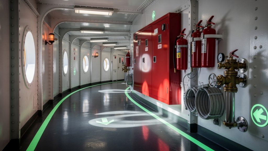
When we think seriously about understanding marine fire control signs, we have to link the neat lines on paper with the actual signs mounted at each hydrant, release station, or escape door. The same symbols appear again, but now they are printed on tough, often photoluminescent plates that people can see through smoke and low light.
Understanding SIS Shipboard Fire Control Plan Signs
SIS signs are safety signs that copy the fire control plan symbols and place them directly at the related equipment. ISO 24409 sets the rules for how these signs are designed, including their size, colors, and minimum performance standards. Signs must be mounted on bulkheads or directly next to the equipment, at eye level where possible, so they are easy to spot when someone is moving quickly.
Because fires can cut power, many SIS signs use photoluminescent material so they glow after the lights go out. They also need to stand up to salt, sunlight, and impacts without fading or cracking. When we work on understanding marine fire control signs, we remind vessel operators that these signs help both trained crew and outside responders who may not know the layout. Supplementary text in the ship’s working language can be added where helpful, especially for instructions such as “Release Station” or “Emergency Fire Pump”.
Combination Signs Symbols Plus Supplementary Information
In many cases, a single symbol does not tell the whole story, so combination signs bring several pieces of information together in one place. A typical example might show the extinguisher symbol with brief text such as “CO2” or “Water” and a small panel giving capacity. Directional arrows can be added to point toward equipment that is not directly visible, such as a hydrant around a corner.
Identification panels with numbers help match signs to the entries on the fire control plan, so someone can say “we used extinguisher 3‑12” and another person can find it on the drawing. When we keep understanding marine fire control signs in mind during sign design, we think about how a mixed crew and external firefighters will read combination signs under stress. Clear symbols, short text in the right languages, and sensible arrow directions keep confusion to a minimum.
Keeping Compliance And Operational Readiness
Compliance with fire control sign requirements is not something we tick off once and forget. Ships change over time when spaces are converted, systems are upgraded, or new equipment is installed. Every change can quietly break the link between the real ship, the fire control plan, and the SIS signs.
When we commit to understanding marine fire control signs, we see that safety depends on three parts working together. Plans must match reality, signs must match the plans, and the crew must know how to use both in an emergency. If any of these three is weak, inspection findings increase and real‑world risk grows.
A common comment from experienced captains is, “If the drawing, the ship, and the signs disagree, the fire will find the gap.”
Maintaining Accurate And Current Fire Control Plans
Fire control plans need to show the vessel as it exists now, not as it looked at delivery. Any modification that affects fire boundaries, fire‑fighting equipment, detection systems, or escape routes should trigger an immediate drawing update. That means revising the symbols, adjusting the legend, and replacing all displayed copies of the plan, including the external set in the weathertight enclosure.
Keeping class and flag state in the loop is also part of this work, especially for major refits. Surveyors and inspectors often check the plans first, then walk the ship to see if what they find matches what is drawn. When we take understanding marine fire control signs seriously, we treat plan updates as part of every change project, not as an afterthought.
Crew Training And Emergency Drills
Even the best plans and signs are only tools, and people must know how to use them. SOLAS requires regular fire drills, and these drills should include time for the crew to find equipment using both the fire control plan and SIS signs. Good exercises might ask one team to locate a specific hydrant, release station, or EEBD starting from a given cabin, while another team traces escape routes on the plan.
Training should also cover movement in low‑visibility conditions, making use of photoluminescent signs and floor markings. On many ships, crews come from several countries, so we need to check that everyone understands the symbol language and any text that appears on signs. When we embed understanding marine fire control signs into normal training, we turn those drawings and plates into real, practiced behavior.
Physical Sign Inspection And Maintenance
Physical signs age, get knocked, painted over, or removed during refits. Regular inspections of all SIS signs help catch these issues early. Checks should look for cracks, fading, missing fasteners, and any signs that a sign has been moved away from its proper position.
Photoluminescent signs should be tested to make sure they still glow for a reasonable period after lights go out. Any damaged or missing signs need quick replacement with ones that match the current standards and the fire control plan. When we link maintenance with understanding marine fire control signs, we treat these checks as part of normal safety rounds, not as a rare special task.
How Safety Sign Hub Helps With Marine Fire Control Sign Compliance
At Safety Sign Hub, we focus our whole business on marine safety signage, so fire control signs are not just one product line among many. We work with ship owners, operators, and safety officers across Australia, the Asia‑Pacific region, and beyond who need clear support with understanding marine fire control signs and keeping them compliant over time.
Our range covers the full symbol set needed on a vessel: structural fire protection markings, fire-fighting appliance symbols, detection and alarm signs, and escape route and EEBD signs. Every item is designed around IMO resolutions such as A.952(23) and A.1116(30), together with ISO 17631 and ISO 24409, so customers can point to recognized standards during audits. We use materials and printing methods chosen for harsh marine environments, including strong photoluminescent performance for low‑light emergencies.
Because we spend our days talking about SOLAS and IMO rules, we help customers match signs to their specific vessel type, age, and trading pattern. That support ranges from clarifying which symbol set applies on an older ship to choosing the right combination signs for new installations. When a customer asks for help understanding marine fire control signs during a refit, we look at the updated fire control plan and suggest a clear, compliant sign package that matches it.
Most general safety suppliers cannot offer this level of maritime focus. By working with Safety Sign Hub, operators gain a partner who watches regulatory changes, keeps product designs aligned with those changes, and helps turn fire control plans into complete, on‑board sign systems. That combination gives real peace of mind when class surveyors or port state control officers step on board and start checking how theory and practice line up.
Conclusion
Marine fire control signs form a shared language between ship crews, shore firefighters, inspectors, and managers. When we put real effort into understanding marine fire control signs, we see that they are far more than a paperwork requirement. They tell us where fire can spread, where equipment is located, how alarms are managed, and how people can escape when conditions get bad.
This language is built on a solid base of SOLAS, IMO, and ISO standards that keep ships across the world working from the same set of expectations. Structural fire protection symbols show passive defenses, appliance symbols show active fire‑fighting tools, detection symbols show how fires are spotted, and escape symbols show how lives are protected when containment is no longer enough. Color codes, letters, and numbers add the fine detail that turns simple icons into clear operating information.
Real safety depends on three things working together: accurate fire control plans, correctly installed SIS signs, and crews who train with both until the symbols feel familiar. Because vessels and regulations change over time, this work never really stops. At Safety Sign Hub, we support that ongoing effort by providing compliant, durable signage and by helping operators read and apply the relevant standards.
The best next step is a simple one. Review the current fire control plans and signs on board, test crew knowledge during the next drill, and identify any gaps between plan, sign, and practice. When help is needed with understanding marine fire control signs or updating them, partnering with a specialist gives confidence that every symbol on the ship does its part to protect crew, cargo, and the vessel itself.
FAQs
Question 1 What Is The Difference Between IMO Resolution A.654(16) And A.952(23)?
IMO Resolution A.654(16) is the older set of graphical symbols used for fire control plans on ships built before 1 January 2004. IMO Resolution A.952(23), adopted in 2003, is the updated symbol set that applies to ships constructed on or after that date. When we are understanding marine fire control signs, we may meet either set, depending on a vessel’s age, but A.952(23) offers closer alignment with ISO standards and more refined symbols.
Question 2 Are Fire Control Plans Required On All Types Of Vessels?
SOLAS Chapter II‑2 requires fire control plans on all ships covered by its rules. That usually includes passenger ships of any size and cargo ships of 500 gross tonnage and above on international voyages. Some flag states extend similar requirements to smaller vessels or ships on domestic routes. Anyone understanding marine fire control signs for a fleet should check flag rules for smaller or exempt vessels, as formal exemptions are rare and must be clearly documented.
Question 3 How Often Must Fire Control Plans Be Updated?
There is no fixed calendar interval for updates, because plans must match the ship as it exists. Any modification to fire systems, structural divisions, or fire‑fighting equipment should trigger an immediate revision to the fire control plan. Regular inspections and surveys by class or flag also serve as checkpoints to catch any mismatch. From a practical point of view, understanding marine fire control signs means treating plan updates as part of every change project, not as optional paperwork.
Question 4 What Are SIS Signs And Where Must They Be Installed?
SIS signs are Shipboard Fire Control Plan Signs that copy the symbols from the fire control plan and place them at the location of the actual equipment. ISO 24409 sets design and placement guidance for these signs, including visibility and photoluminescent performance. They should be mounted on bulkheads or directly beside items such as hydrants, extinguishers, release stations, and escape doors. When we focus on understanding marine fire control signs, we see SIS signs as the bridge between the drawing on the wall and real‑time actions during a fire.
Question 5 Do Crew Members Need Specific Training On Fire Control Symbols?
Yes, crew training on fire control plans and symbols is a core part of SOLAS fire drill requirements. Training should include practical tasks such as finding specific equipment using the plan, following escape route arrows, and identifying different extinguishing agents from signs and markings. Records of these drills and training sessions need to be kept for inspection. When we build understanding marine fire control signs into normal drills, symbols stop being abstract diagrams and become practical tools that guide real decisions in an emergency.